
For each production method there are production rules that can also depend on the material and the material thickness. With the teknow wizard you can check your drawing and change it so that it is ready for production. For this reason, teknow asks the manufacturing method and material in advance – otherwise the wizard would not be able to determine the appropriate rule set. But you can always go back to the selection and change the method or material – when you open the drawing again, the new rain will be loaded.
These are the main functions of the wizard:
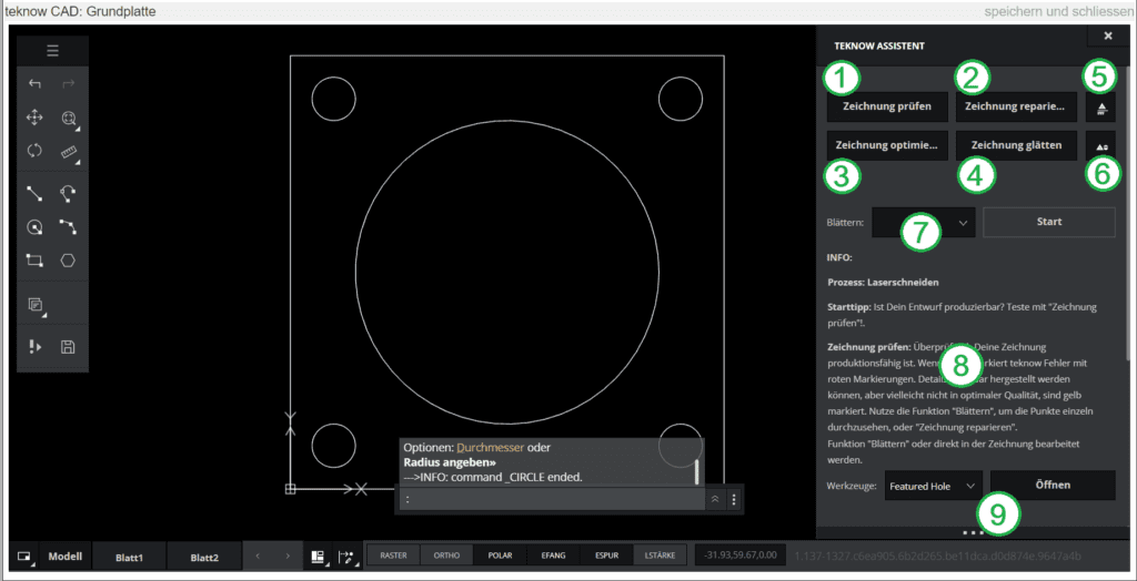
(1) Check design:
Checks whether your drawing is ready for production. If so, teknow shows a preview of the part in green to the right of your drawing. If not, teknow marks errors with red markings. Details that can be produced, but may not be of optimal quality, are highlighted in yellow. Use the function “Repair drawing” or “Scroll” to look through the points one by one.
(2) Repair errors:
Tries to automatically fix any errors in the drawing. Duplicate elements are deleted, small gaps in the contour are closed, and impermissible curve functions such as splines are converted. Remaining errors must be corrected with the “Scroll” function or directly in the drawing.
(3) Optimize drawing:
Tries to reduce the number of line elements by connecting lines. This is sometimes useful for imported drawings.
(4) Smoothen drawing:
Smooths out noisy contours, such as those often created in drawings from converted scans. The function is not intended for technical drawings.
(5) Purge issues:
Deletes the messages generated by the “Check drawing” function.
(6) Toggle isues:
Temporarily hides or shows the messages generated by the “Check drawing” function.
(7) Browse:
calls up the points found by the wizard one after the other, gives explanations and hints and, if possible, makes suggestions for manual or automatic elimination of the problems.
(8) Info:
The wizards’s messages appear here
(9) Tools:
Access special drawing tool pages, such as B. for threads, countersinks or bevels. Here is a separate help page for the drawing tools.
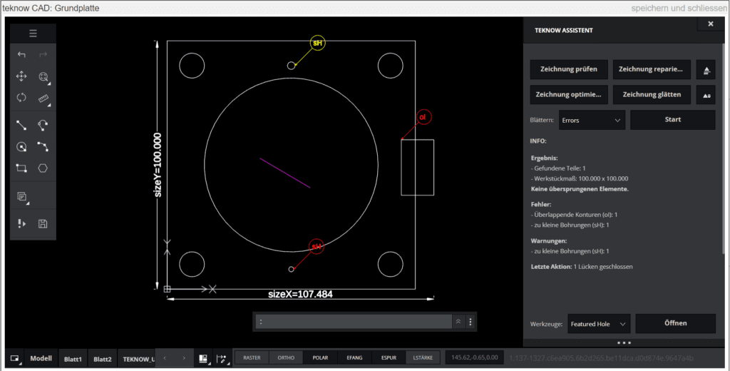
The following example shows a base plate with different holes, an overlapping rectangular contour on the right that intersects the contour of the base plate, and an unconnected line within the central hole.
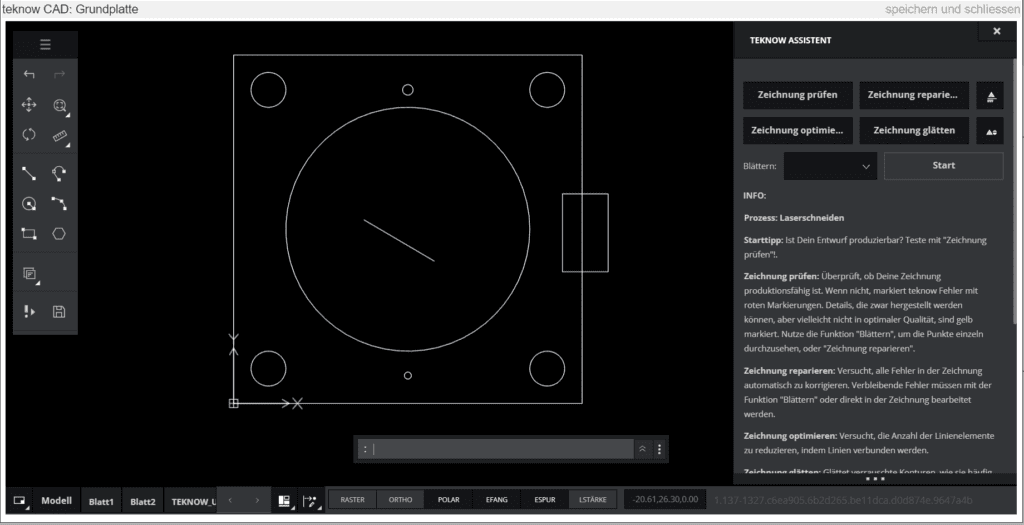
A click on “Check drawing” gives the following feedback:
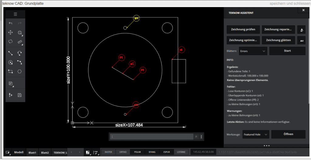
In the wizard window you will find a legend for the points found, here for example “Free points”, these are the end points of lines that end without a connection, or “Intersecting contours” in the case of the rectangle. You can now edit the marked elements manually, for example trim the rectangle as shown above, or delete it. Alternatively, the wizard can independently try to make the drawing producible. To do this, click on “Repair errors”. Deleted elements are moved to a backup layer (line color magenta). In our case, the result looks like this:
The disconnected line within the central hole could be removed automatically. If this is not desired in an individual case, you can mark the element with the mouse and assign it to the active layer using the properties palette. The rectangle that intersects the contour could not be automatically deleted because the assistant cannot decide which is the “correct” geometry of your workpiece – do you want to manufacture the rectangle or the rest? You can delete the rectangle by hand, trim it if you want the base plate to have an indentation or bulge there, or use the “Browse” function for troubleshooting, as shown below. A click on “Start” in the “Browse” line opens the following page:
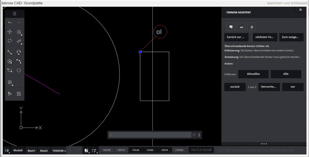
The wizard shows an enlarged section of the drawing with the highlighted error. Also, the wizard indicates the type of error (overlapping contour), provides an explanation and instructions on what to do to rectify the problem. Below, you will find possible options for how the error can be corrected automatically. Here you can delete the marked contour at the push of a button. In addition, you can use the “All” function to remove all the same errors at once. Here in the example we click on “Remove: current”. The wizard then jumps to the next error, the too small hole.
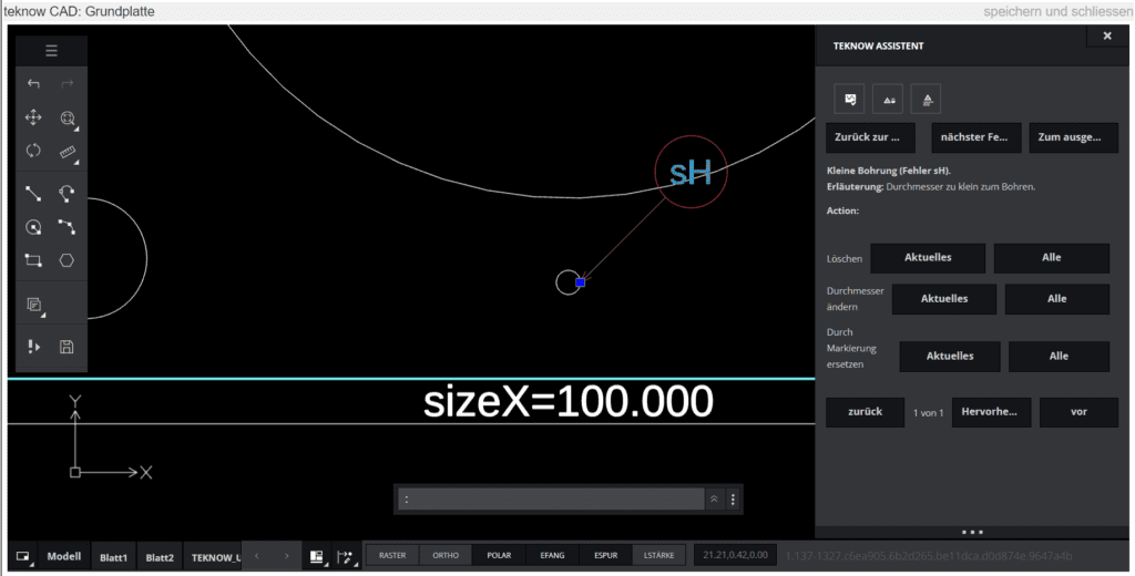
In addition to “Delete”, there is also the option of automatically enlarge the diameter to the minimum that can be produced, or of replacing the hole with a marking cross (cross as laser inscription, see the following picture below). Here, too, there is again the option of clearing up all errors of the same type in one action.
The drawing can contain elements that do not stand in the way of production, but which may not be producible in optimal quality. This mainly applies to small bores or fine web-like structures. In these cases, the wizard gives warnings marked in yellow to indicate small bores or small webs near the manufacturing limit.
These fine details may tarnish when cutting with the laser due to the effect of the heat, very small structures can melt, and the edges of the holes may be somewhat frayed. Here you can decide whether you want to produce the workpiece as drawn – possibly accepting the effects mentioned – or rather change the details. You can find help with the decision here. In the example this concerns the hole in the picture above. Like the errors, you can also scroll through the warnings and you will be shown options again.
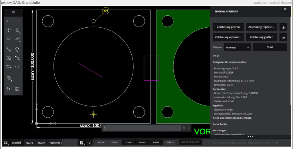
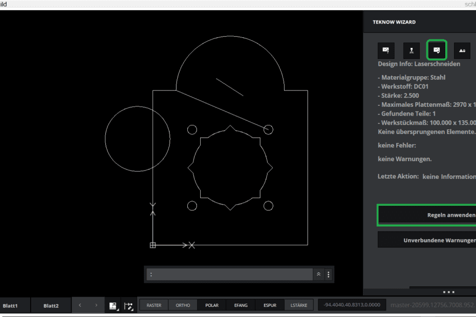
When the wizard no longer reports any errors, the drawing is in a producible state. The workpiece preview in green is then displayed on the left. By clicking on “Close and Save” in the upper right corner of the window, you will return to the workpiece form. The price will be displayed and you can continue with the ordering process.