FAQ
Frequently asked questions
On this page you will find a list of the “frequently asked questions” with their answers. And if you can’t find some information, you can ask us a question using the FAQ form.
FAQs
- How do I create a usable import file (dwg / dxf)?
You can import your own files from other CAD systems into teknow in dwg or dxf format. The format is recognized automatically.
Rules for creating a suitable import file:
The cutting lines must be white. Yellow lines are interpreted as laser marking. Other line colors are ignored. The drawing must be on a scale of 1: 1 in mm dimensions. The drawing should only contain 2D geometry, no blocks and no z-components. It should only contain one workpiece, also no drawing frame or text field. Dimension lines are ignored.
In many cases, the teknow wizard offers you the option of correcting drawing defects at the push of a button. (Color lines white, dissolve blocks, set z-components to zero). Teknow marks points for which no automatic solution is possible. You can then change this manually. As a rule, however, it is better to create a suitable drawing file directly than to correct deficiencies afterwards.
Technical workpieces:
Select export settings in such a way that no SPLINEs and no ellipses are generated during the export. As a rule, these curves rarely appear genuinely in technical drawings, but when exporting, circular holes are exported as ellipses or as splines, some programs also display rectangular sections as splines or everything at all. Numerically controled Machines cannot cut either type of curve. These have to be converted back before production, which leads to a loss of accuracy. Bores should not be approximated by straight lines, but should be represented as circles. Otherwise, a very large number of line elements will result from just a few holes. The machine approaches them all individually and accordingly needs a lot of cutting time, which drives up the price – not to mention the loss of accuracy. If there are splines or ellipses in the original drawing, they should not be replaced by too many line elements for the same reason – you may have to experiment a little here.Design pieces:
In the best case scenario, you stick to the same rules as above. However, the accuracy is not in the foreground here, so when converting splines etc. resulting small deviations are tolerated. Alternatively, you can use the teknow wizard to automatically convert these curves into lines. The replaced splines are colored magenta, so you can compare the old and the newly calculated cutting edge and assess the deviations.Drawings converted from scans:
The same applies here: no SPLINEs. The curves must be approximated as arcs or lines. The challenge is to find a meaningful resolution. A drawing that consists of many thousands of 0.2 mm short line elements is of no advantage in production. As a recommendation, the straight length or arc length should not be less than 2 mm. This can be too coarse with fine details – you have to experiment a little here and see whether the result is acceptable for the workpiece. - Can I receive the laser cutouts?
Unfortunately that doesn’t work – the cutouts fall into the waste boxes under the machine, together with the cutting slag. The boxes are emptied at the end of the week, there is then nothing more to assign, and it no longer looks good. Furthermore, the cutouts each have the recess somewhere, that is the point at which the laser drills into the sheet metal and the cutting contour starts, so they are not optically perfect.
- Can I download the dwg file?Project drawings: yes Workpiece drawings: No. teknow uses a number of self-developed notations in the production drawings, for example for warning messages or for manual processing steps. These are not part of the standard and would cause errors in other programs. Furthermore, if necessary, drawings are adapted to the production possibilities, for example by replacing splines with arcs. Since the drawing cannot usually be used for any other purpose, a download function is not available.
- How is the price of the workpieces calculated?
If your workpiece can be produced, teknow will show you the price for one part as well as for two, five, 10 and 50 parts on the workpiece page – after closing the CAD editor. Depending on the number of parts and possibly also other parts ordered, the unit price can drop considerably. The price for a workpiece is made up of variable costs – those that increase with the number of parts – and the fixed costs. Variable costs are, for example, the costs for the machine time (depending on the material, thickness, cutting length, number of grooves) and the material price. The fixed costs include the incoming check of the production file, importing the data to the production machine and accounting, sometimes also a tool creation, as with photo-chemical etching. The fixed costs are distributed over the number of parts ordered. Therefore, the unit price decreases as the number of parts increases. Furthermore, there may be an additional discount for some production methods if you order different parts made of the same material (same machine, same material, same thickness). Then we only have to fetch the material from the warehouse once and place it on the machine. We pass on the saved expenses in the form of a discount – shown in the bottom line in the shopping cart.
- How are the shipping costs calculated?The shipping costs consist of transport and packaging. The packaging is more complex for teknow and therefore a little more expensive than what we are used to from mail order business, as we do not pack any standard items and therefore have to resort to manual labor. We send up to 31.5 kg and dimensions under 120 x 60 x 60 cm³ (including packaging) with a parcel service. We send workpieces that exceed these specifications as bulky goods as long as the added lenghts L + 2xB + 2xH remains below 360cm. Everything above that will be sent with a forwarding agency.
- What is a bonus for?
One of teknow’s main ideas is to share drawings and learn from one another. To give all users a little impetus to share drawings with others, there is a bonus system. If someone reproduces your workpiece, teknow will credit you with a bonus. The bonuses are automatically offset against the next order. The bonus is € 1.
You can set the visibility of your workpieces on the workpiece side, also during the order or afterwards. In the “Visible” status, your ordered workpiece is visible to everyone, and you allow it to be copied by other users. You can cancel the approval at any time with effect for the future. Your workpiece must be ordered so that others can see and copy it – this condition ensures that only relevant drawings that can be produced appear in the hit list.
- Producing despite warning messages - or not?
If the teknow wizard issues warnings, there are details in your drawing that may not be able to be produced in optimal quality. This mainly applies to narrow webs. In many cases, the workpiece can still be produced. Sometimes the quality of a detail is not important either, for example when it is just a matter of bars to connect the actual parts. It is not possible for the software to identify such cases. You can then decide how you want to proceed – produce anyway, or redesign. This page gives you assistance with a few examples.
Note: If you produce a drawing with warning messages, defects in the areas marked with the warnings are not grounds for complaint. Production takes place at your own risk with regard to these locations.
Example 1: ventilation grille with long narrow bars
The ventilation grille, 300 mm high, 600 mm long, is to be cut from 10 mm steel. The five bars are only 4 mm wide and 560 mm long. Here it is very likely that the webs will warp due to the heat input and will not be parallel. Since it is difficult to straighten the bars due to the lack of space, deviations can hardly be remedied afterwards. Therefore, this workpiece should not be produced in this way.
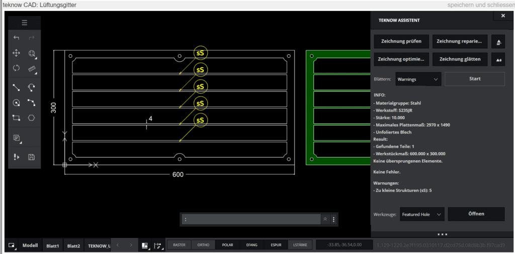
There are a number of ways to make the workpiece more producible. The material thickness could be reduced or the webs widened. It would also be possible to draw in some crossbars. If the dimensions have to remain unchanged, only the frame can be cut, and you cut the rods from a rectangular rod 4 x 10 mm and weld them in (or the locksmith will do that). In order to find the correct position, you can make notches in the frame.
These are the limit values for web widths:
Warnings:
Material thickness up to 3 mm: web width less than twice the material thickness Material thickness over 3 mm: web width less than one and a half times the material thicknessError:
Material thickness up to 3 mm: web width less than half the material thickness Material thickness over 3 mm: web width less than a quarter of the material thicknessExample 2: mechanical parts
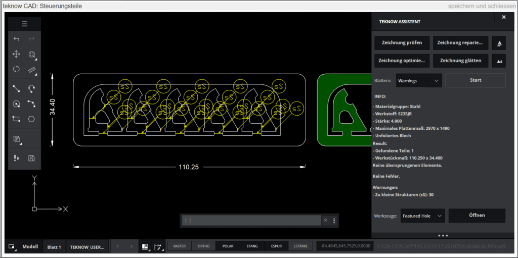
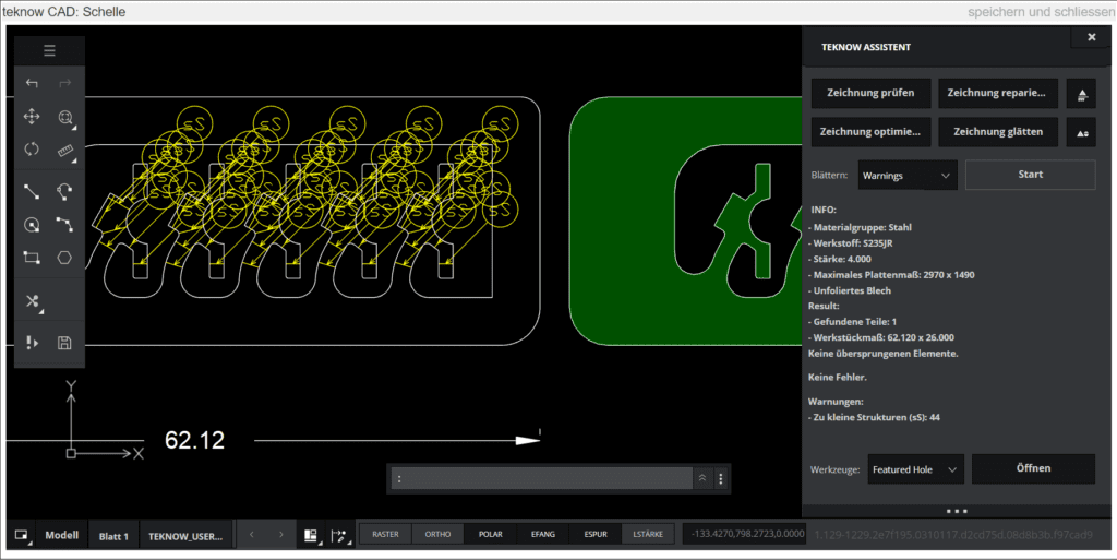
The parts belong to a locomotive model. They are arranged in a frame so that they can be clamped more easily for further processing. A relatively large number of warnings are displayed in these two drawings because the parts are repeated several times.


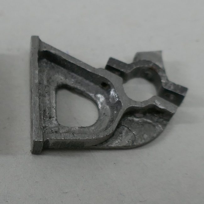
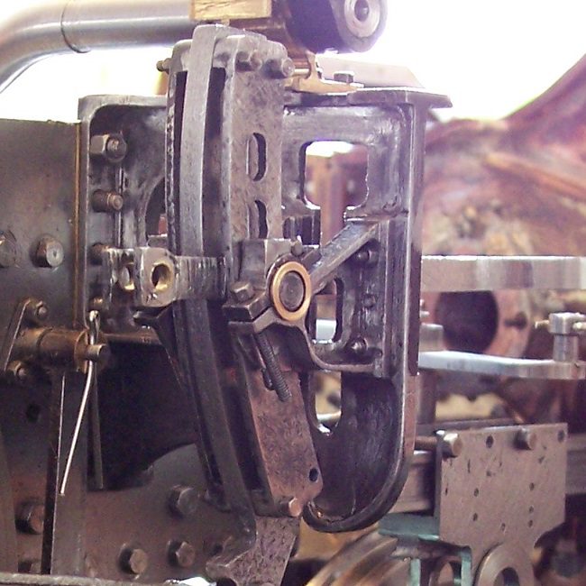
Some of the warnings concern the connections between the parts and the frame – these can usually be ignored, as it is just an auxiliary construction that will be removed later. There are also warnings that concern the actual parts. Here you have to weigh up. In this case, the parts are difficult to produce “by hand”. They will be processed further below, which gives the opportunity to correct distortion or melting. Any discoloration is irrelevant. A few more parts are produced to compensate for failures. The parts could be manufactured and processed with a little loss, as the following two pictures show: on the left the parts in the finished state, on the right installed.
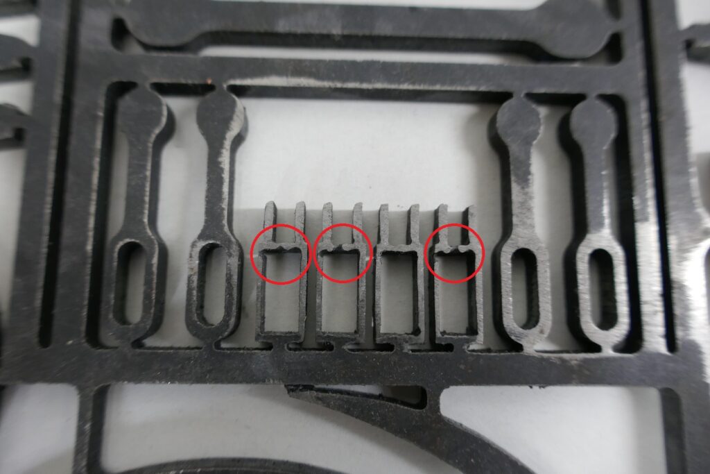
The parts on the following picture show examples of light melts. In this case the result was usable.

Such defects on parts that are no longer reworked and that should have a high optical quality are not acceptable. An example of such a part is a doorbell sign or a plate that contains filigree letters.